By Stuart Mortimore
Power generation, for many, is a black art that is peppered with common words that have uncommon meanings. Indeed, many a person could not tell his alternator from his exciter, and the prospect of a fault with his up-shaft conductors could cause any self respecting power station engineer to break out into a sweat!
Like most things in life, once the basics have been explained the fog will lift sufficiently for most people to grasp, at least in outline, the matter at hand. The details, however, will remain the preserve of the specialist electrical engineer who has had experience in the relevant electric field (no pun intended). Such experience is often vital in investigating failures or fires involving such complex machinery.
Generators are specialist electrical machines that are used to generate electricity. The electricity may be direct current (dc) or alternating current (ac). An alternator, on the other hand, is a specific type of generator that will only generate alternating current and it is these machines that generate the electricity that we use in our homes and workplaces. We shall therefore concentrate on them here.
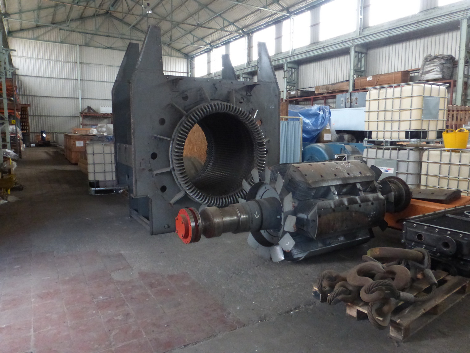
An alternator comprises two main parts. The first part is effectively a steel tube that remains stationary: for this reason it is called the stator. The other part is effectively a steel cylinder that is threaded up the centre of the stator and which rotates; this part is called the rotor. Both the stator and the rotor have coils of copper wire wound onto them and these coils are known as the stator windings and the rotor windings.
In 1831 Michael Faraday discovered that if a magnet was moved within a coil of wire, electricity would be generated within the coil. This mechanism is called electromagnetic induction. It was also discovered that if one applied a direct current to a coil of wire, an electromagnet would be produced. These two effects, which are effectively the converse of each other, were amplified appreciably when the coils of wire were wrapped around steel frames, or formers.
Combining these principles it is easy to see that if a battery was connected to the rotor winding of our alternator, and if the rotor was then rotated within the stator, an alternating electricity supply would be generated in the stator windings for as long as the battery was able to supply the rotor current and the rotor was still turning.
Modern alternator rotors are generally turned by steam turbines, water turbines, gas turbines or, in the case of smaller sets, by diesel or petrol driven engines. Owing to the limited life of batteries, the rotor current (which is more generally known as either the field current or the excitation current) is not supplied by batteries. Rather, specialist pieces of equipment called exciters are used. Exciters may be either of the static variety, which means they comprise banks of electronic components that provide the direct current for the rotor winding, or of the rotating variety. In the latter case a permanent magnet is used to generate electricity in a small (or pilot) exciter, and the pilot exciter output is used to provide the rotor current for a main exciter that in turn provides the rotor current (or excitation) for the alternator. These machines are all connected onto a common shaft and the energy that is needed by them is provided by the same machine that turns the alternator rotor.
The voltage that is generated by an alternator is determined by a number of factors that include the speed of rotation of the rotor, the amplitude of the rotor current and the characteristics of the electrical load to which the alternator output is connected. For this reason a specialist piece of equipment called an automatic voltage regulator (or AVR) is required to measure the output of the alternator and to vary the rotor or excitation current of the machine such that the alternator voltage is maintained at the desired value. Such devices also play a role in rectifying (converting to dc) the alternating current output of the pilot exciter so that it can provide the direct current that is needed for the rotor of the main exciter. Further rectifiers convert the main exciter output from ac to dc so it can provide the alternator rotor current, and the current is fed from one device to the next by copper conductors that run up the shaft or the machine. These devices, you will no doubt have deduced, are the up-shaft conductors to which reference was made earlier and it will now be apparent that a fault with them will result in a loss of excitation, the loss of generation and hence, for the power station engineer at least, severe perspiration.
High power electrical equipment can fail mechanically or electrically and in some cases one type of failure can lead to the other. Whether the failure or failure string involves a fire or loss of generating capability owing to mechanical breakdown the application of materials science, mechanical engineering and electrical engineering in a structured way can identify the cause of the initial fault.
Principal Contacts
Stuart Mortimore, Glasgow Office
Bernard Bourdillon, London Office
Peter Jowett, Ilkley Office
David Bailey, Kenilworth Office
Mark Slater, Basingstoke Office
Mark Cousins, Cardiff Office