By Dr Jim Mercurio
The primary focus of any fire investigation is to establish where and how the fire started but, in the larger scale incidents we deal with, consideration is also given to how the fire spread. One aspect that can be related to this is investigating the operation of any fire protection systems. This topic can be particularly important in situations where an insurance policy has specific conditions or endorsements related to firefighting equipment, or where local regulations require that fire protection systems be provided.
In the Middle East, many of the premises we attend are fitted with a fire pump set that supplies pressurised water to hose reels and a sprinkler system. The installation of sprinkler systems is commonplace in residential tower blocks in the region and, in the wake of the Grenfell Tower incident, there are calls for this to be the case in the UK. In addition, it is not uncommon for large storage facilities, production lines and factories to be fitted with fire pumps and sprinkler systems.
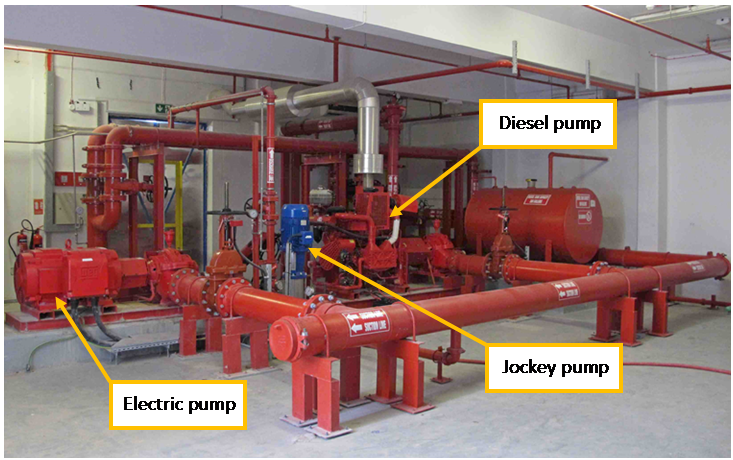 Image 1: A fire pump set comprising a jockey pump, electric pump and diesel pump.
Fire pump sets vary in size and complexity but a common fire pump set design, such as the one shown in the image above, comprises three pumps. These pumps are often referred to as the ‘jockey pump’, ‘electric pump’ and ‘diesel pump’. The jockey pump is a relatively small capacity pump and its primary role is to maintain system pressure whilst the system is not in use (i.e. to keep the system primed). Operation of a sprinkler head, or use of a hose reel, will cause a drop in system pressure that the jockey may not have the capacity to restore. This pressure drop is detected by control panels connected to the pump set called ‘pump controllers’, which have pressure sensors in the pipework. When set to automatic mode, the pump controllers would then automatically start up the electric pump at a predetermined pressure to meet the water demand. The diesel pump is intended to act as a back up in case the electricity supply to the electric pump is lost (e.g. if the power to a building is isolated during a fire incident), or if the demand on the system is greater than the electric pump can supply (e.g. if multiple sprinkler zones activate).
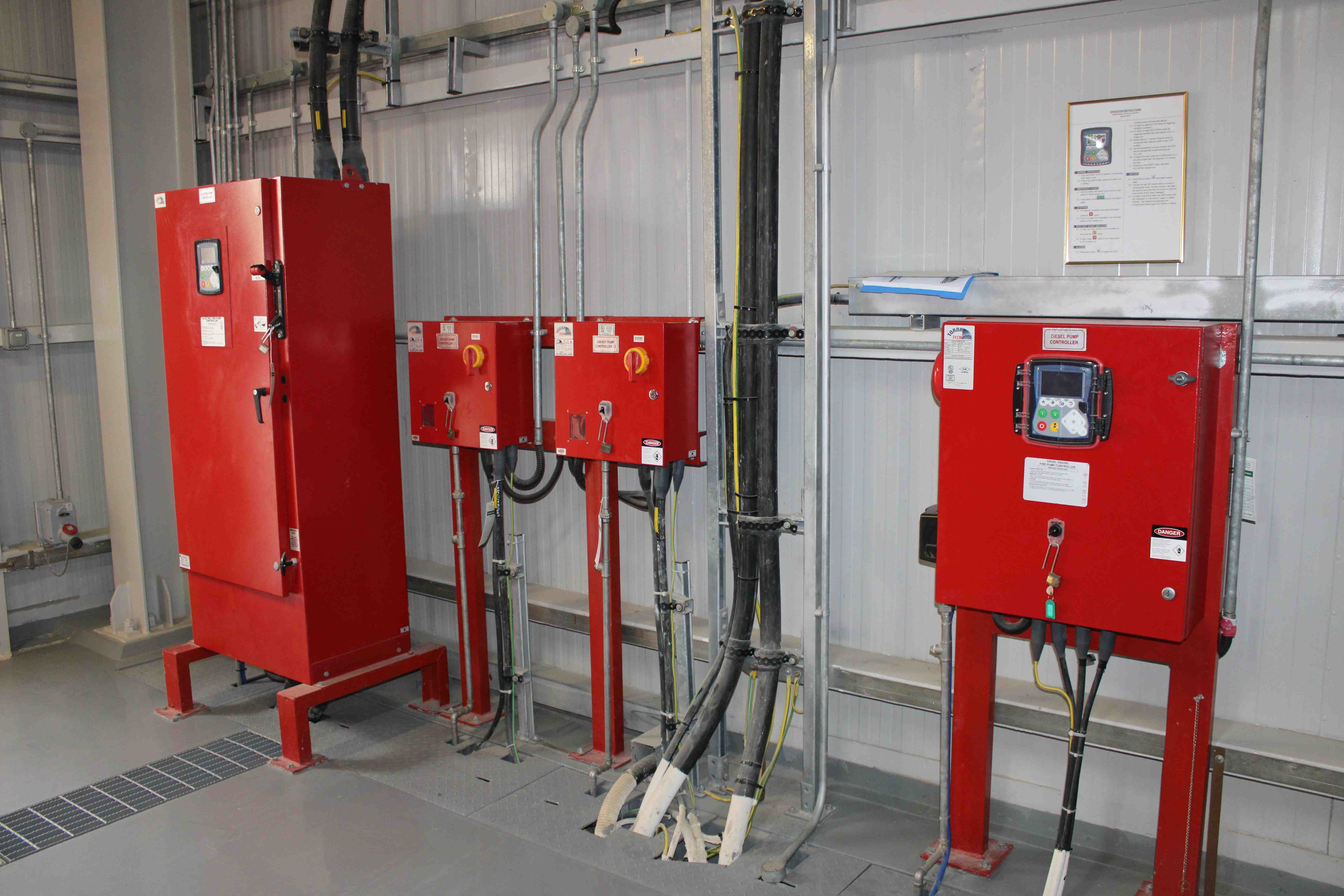 Image 2: An example of the pump controllers associated with a fire pump set.
As can probably be appreciated from the images above, the equipment can appear quite complicated on first viewing, but identifying each of the pumps and establishing their suction and discharge sides is usually straightforward. In this regard, the suction side can be identified by locating the water storage tank(s) from which the pumps draw water. The pumps then typically deliver pressurised water into a discharge manifold that can be split into several branches, which allows pressurised water to be supplied to different equipment (there are often separate branches for sprinklers and hose reels). The schematic diagram below demonstrates a typical arrangement and sketching out a drawing like this whilst inspecting a pump set can help in understanding how a particular system works.
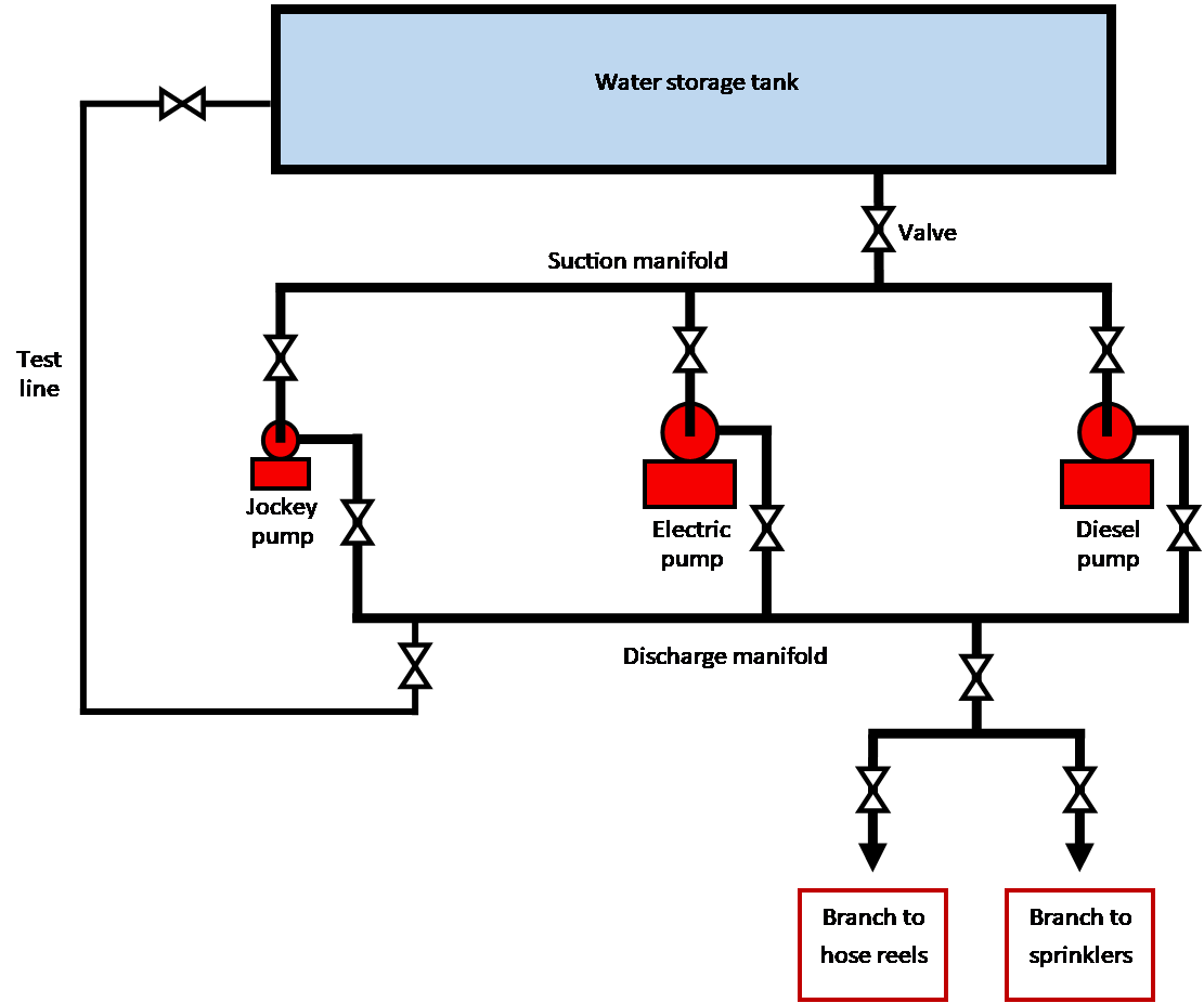
Image 3: Schematic diagram of a typical fire pump set.
As can be seen in the diagram above, there are a series of valves in the pipework associated with the fire pump set and the equipment it supplies. These valves can be used to isolate certain parts of the system, for example when the pump set or a part of the system is being tested or inspected. Outside of any such tests or inspections, certain valve handles are sometimes locked in the ‘open’ position using chains to prevent the valves from being closed, which could render a pump set inoperable.
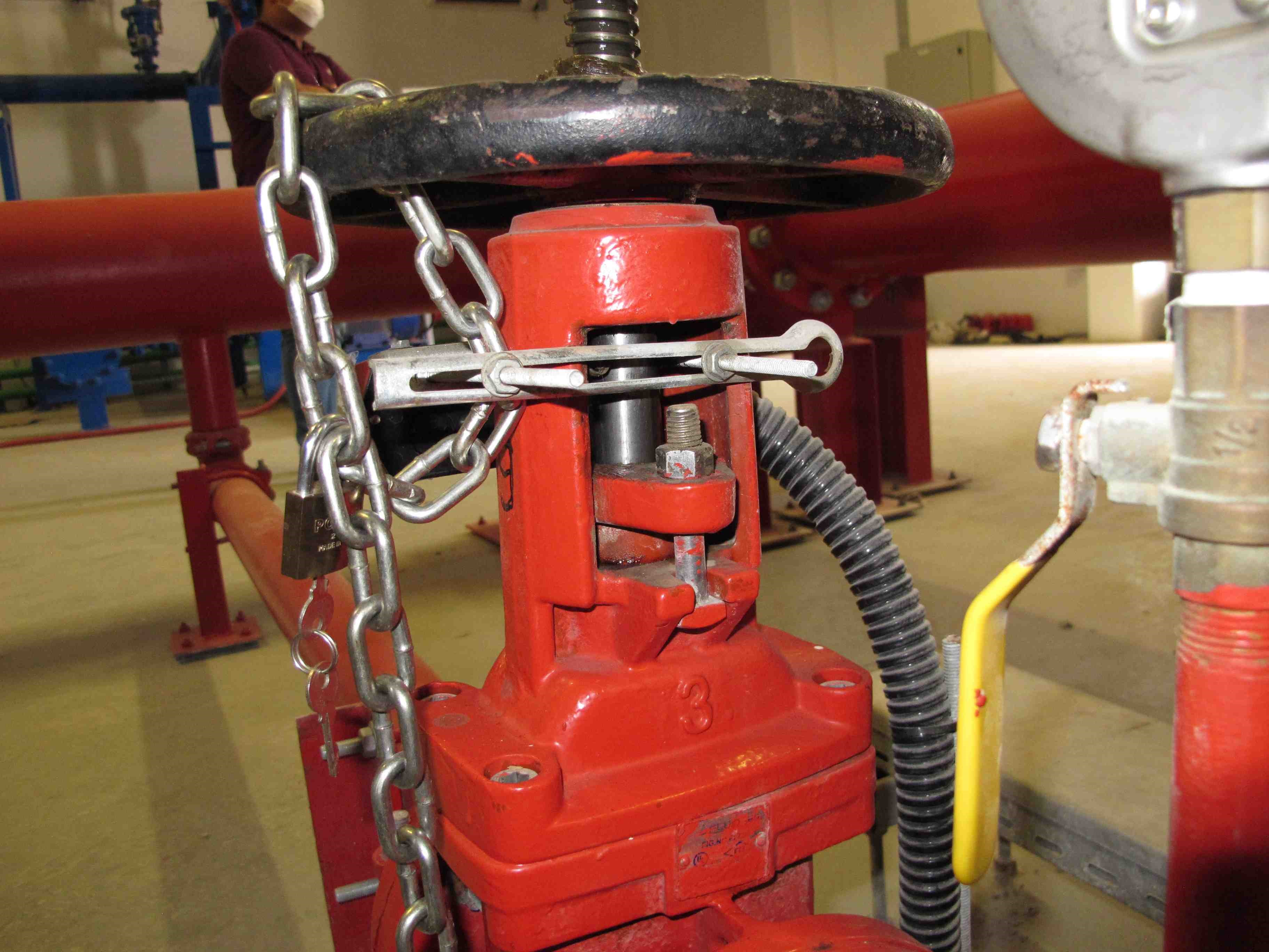
Image 4: A valve handle locked in the ‘open’ position using a chain and a padlock.
In some installations, there are valves downstream of the discharge branches. For example, in residential towers there are usually valves in the sprinkler pipes on each floor called ‘zone control valves’, which can be used to isolate certain sections of the pipework. These valves are useful as they can allow the rest of the sprinkler system to remain operable if there is a fault in one area. An example of this would be to isolate the sprinkler zone where a fire has occurred so that the rest of the building can remain protected. Zone control valves can also be used to isolate sprinkler zones for maintenance purposes, although it is possible that a zone control valve could be inadvertently left in the closed position, meaning that no water would be pumped to the sprinklers in that area in the event of a subsequent fire.
Assessing whether a fire pump set and sprinkler system had been functional at the time of an incident and had operated as intended in response to the fire can sometimes be straightforward. There might be CCTV footage and/or obvious physical evidence at the scene that clearly shows the sprinklers, and thus the fire pumps, had operated. This physical evidence includes water distribution patterns to ceilings/walls next to any open sprinkler heads, such as those shown in the images below, which are created by the water discharged from the sprinkler head. In practice, however, it is not always this simple and a thorough assessment of the entire system is often required. This is typically the case when premises have been severely damaged and there might not be any remaining evidence, such as the water distribution patterns just mentioned, to show whether the fire protection systems had operated.
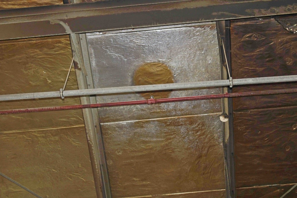
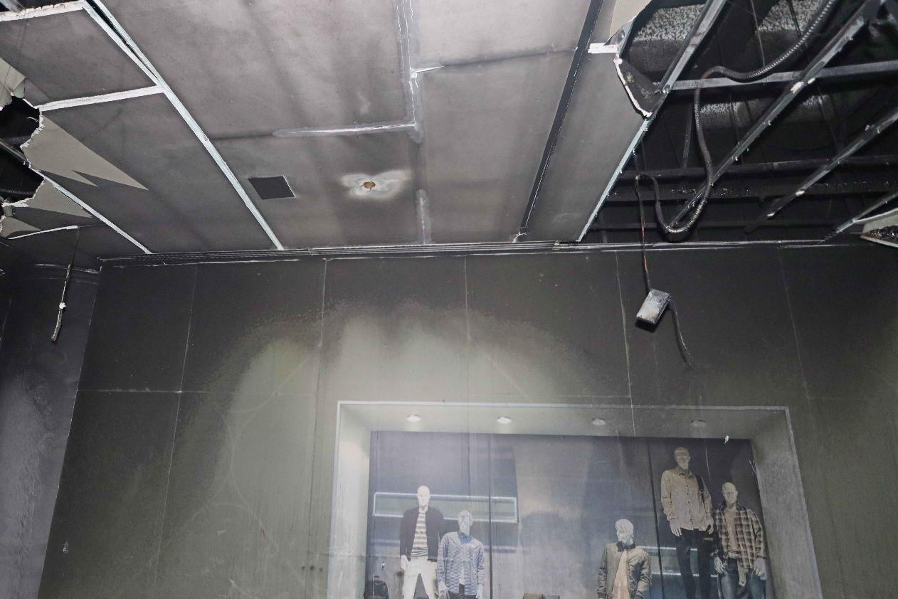
Images 5 & 6: Examples of water distribution patterns that demonstrate the sprinklers had operated.
A thorough assessment of the system would involve a detailed inspection of all the equipment to determine its condition and the status of the various control switches and valves. This could reveal that the pump controller switches were not correctly set or that one or more of the valves were closed, which may have prevented the pump set from supplying pressurised water. Inspection of the equipment could also reveal other issues and we experienced a case where a circuit board was missing from inside one of the pump controllers, which had prevented the relevant pump from running. This had not been noticed during a previous inspection by another party and demonstrates that crucial evidence can easily be missed unless the person carrying out the inspection is familiar with such systems.
In addition to physical inspections, a thorough assessment of the system could also involve studying any operational data recorded by the fire alarm system and/or building management system and the pump controllers. Indeed, modern pump controllers can retain extensive event and operational logs that can be extracted after a fire. As well as recording the dates and times of pump operation, they can also indicate whether pumps were started in manual or automatic mode, whether any faults occurred, and can display historical data.
Therefore, it can be seen that a proper and correct assessment of the operability of a fire pump set and/or sprinkler system requires a detailed inspection to be undertaken by somebody familiar with how such systems operate. Burgoynes has extensive experience in this field and an assessment of this kind can be added to our scope of works when we are instructed to investigate the cause of a fire. The prompt appointment of one of our investigators is recommended, so that the crucial evidence can be documented and recovered before the scene is disturbed and evidence is potentially lost.
Please contact your local Burgoynes office for more details, or to discuss potential instructions.