By Stuart Mortimore
Transformers have long been the unsung heroes of power systems. No, I do not mean the toy cars that can be changed by a few swivels into a powerful robotic superhero and back again. I am referring instead to the workhorses of energy distribution systems that can change the voltage of power supplies both up and down. These items are an important part of our energy distribution system and they can arguably lay claim to being one of the first green energy devices.
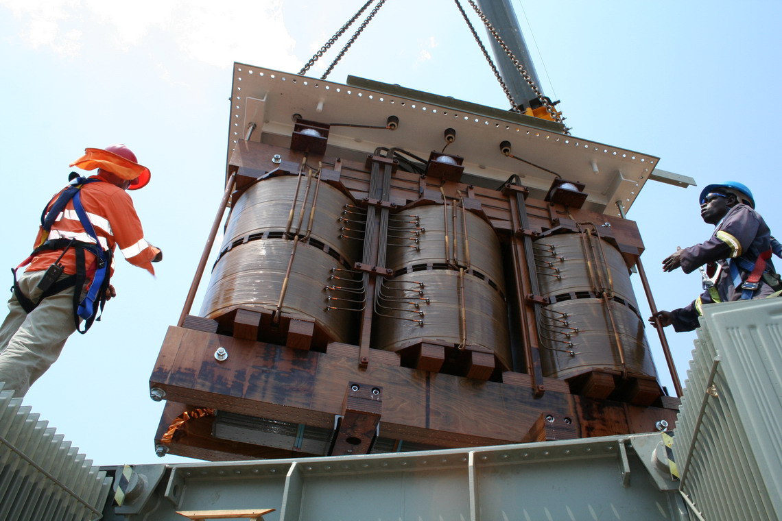
A transformer comprises a laminated steel former, typically approximating in form to a rectangle or a squared off figure of 8 that is lying on one side. Copper, or occasionally aluminium, windings are then looped over the upright parts of the cores as shown in the first photograph below and the assembly is then protected within an enclosure or tank. A simple single phase transformer would have two such windings, one of which would be the primary winding and the other of which would be the secondary winding. A simple three phase transformer, in contrast, would have three such primary windings and three secondary windings. The principle is the same so, as it is simpler to understand, let us consider how a single phase unit works.
Electromagnetic theory underlies the operation of a transformer. Back in the 18th Century it was discovered that when a coil of wire was wrapped around a steel (or iron) core, the core would become magnetised when an electric current was passed through the coil. It was further found that when a second coil of wire was wrapped around the same core, and when the magnetic field strength in the core changed in response to alterations in the current in the first coil, a varying voltage was induced in the second core. Extrapolating from this principle it was further found that when the first winding was carrying an alternating current, an alternating voltage was induced in the second winding and this could be used to drive an alternating current in any circuit that was connected to the winding.
The important thing to remember about a transformer is that the voltage ratio between the primary and secondary windings is the same as the ratio of the number of coils of wire in the two windings. As a result, and expressed less mathematically, if one applied 100 Volt to a primary winding that had 100 coils of wire, a secondary winding that had 1000 coils of wire would develop a voltage of 1000 Volt across it. One cannot, however, get anything for free in this life so the power that is taken out of a transformer cannot be more than that which is put in. Consequently, if the primary winding carried a current of 1000 Ampere at 100 Volt, giving an input power of 100,000 Watt (100 kW), the secondary winding could only deliver the same power and hence the output current would be 100 Ampere at 1000 Volt, again 100 kW.
Power losses in transmission lines increase dramatically with the magnitude of the current that is carried by the line: the losses increase approximately in a square law. It follows, therefore, that if one increases the transmission voltage the current, and hence the power line losses, are greatly reduced. In the UK the large transmission lines operate at 400,000 Volt whereas generators typically generate at 20,000 Volt. Even after transformer losses are taken into account, and large transformers have efficiencies in the high ninety percents, the power line losses are reduced by nearly a factor of twenty squared ie four hundred. The reasons for claiming that transformers are green superheroes are therefore readily apparent.
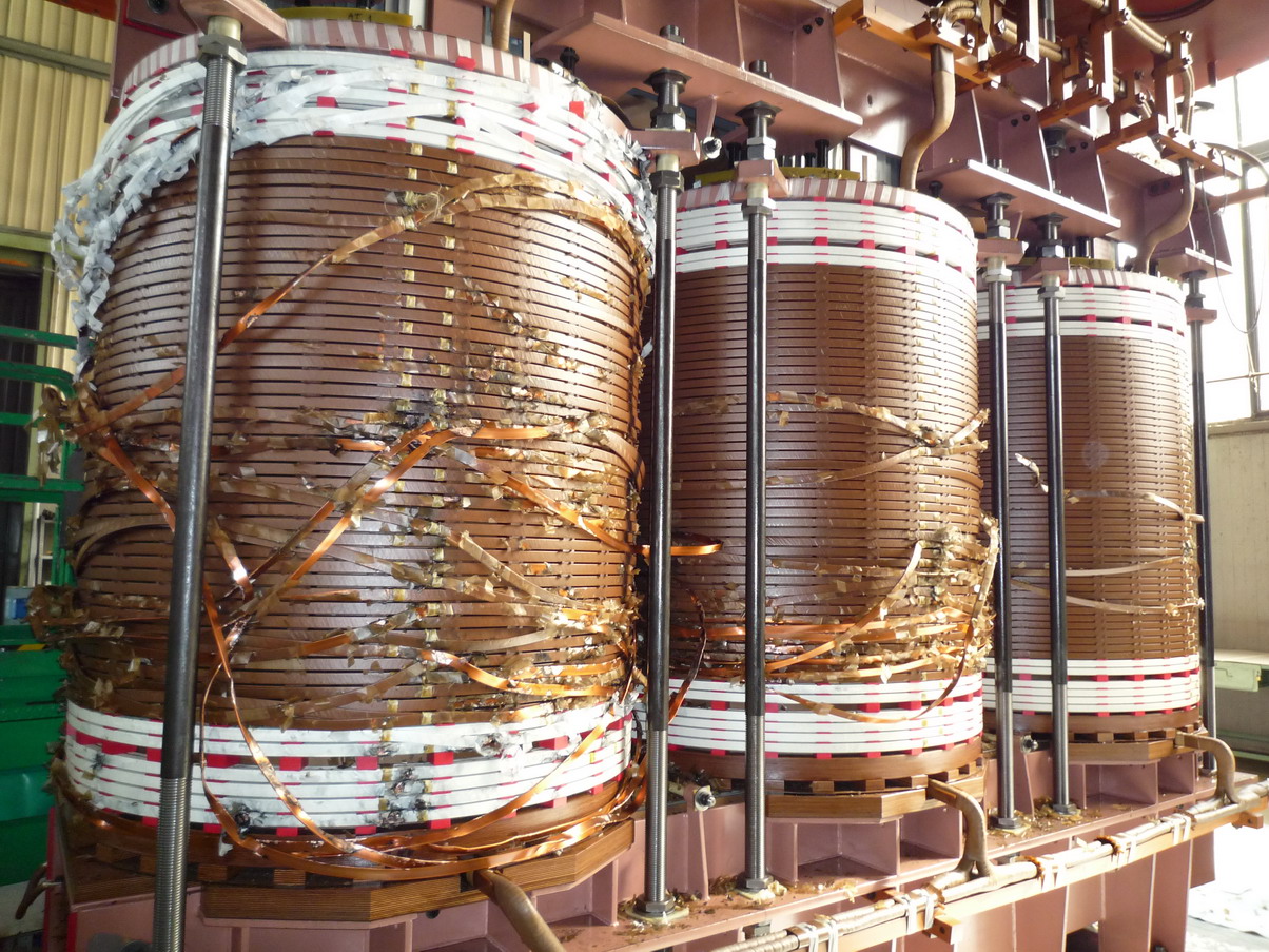
Transformers, like any other item of equipment, can develop problems and, because of the high powers that they carry, when they fail they often fail dramatically and catastrophically: the second photograph shows an example of a large transformer failure. An examination of the remains of the equipment, along with any protection and monitoring data that may be available, will often enable the cause of the failure to be pinpointed by a suitably qualified forensic electrical engineer. Examples that have been investigated successfully by Burgoynes include failures that resulted from damage that occurred during shipment at sea, insulation failures that could have been detected before catastrophic failure occurred, tap changer (voltage ration changing switch) problems, and bushing (porcelain insulator) failures.